Camless Engine
- Pages: 19
- Word count: 4537
- Category: Engineering
A limited time offer! Get a custom sample essay written according to your requirements urgent 3h delivery guaranteed
Order NowAutomobile manufacturers have recognized the compromises associated with engines that are governed by the rotation of a camshaft. This rotation, the speed of which is proportional to the engine speed, determines the timing of the engine valves. For this reason, automotive engineers must make a decision early in the design process that dictates the performance of the automobile. The engine will either have powerful performance or increased fuel economy, but with the existing technology it is difficult to achieve both simultaneously.
In response to the needs of improved engines, some manufacturers have designed mechanical devices to achieve some variable valve timing. These devices are essentially camshafts with multiple cam lobes or engines with multiple camshafts. For example, the Honda VTEC uses three lobes, low, mid, and high to create a broader power band. This does represent an increased level of sophistication, but still limits the engine timing to a few discrete changes.
The concept of variable valve timing has existed for some time. Unfortunately, the ability to achieve truly variable valve timing has eluded automotive manufacturers. Most variable timing mechanisms were created as tools for the automotive engineer. Their use was limited to the laboratory as a means of testing multiple, “virtual” cam profiles. These early Camless engines allowed for the designers to choose the best cams for the engine under scrutiny, but were less than energy efficient. Furthermore, they were one laboratory machines and were not capable of being mass produced or utilized in an automobile
Chapter Two: Introduction to Camshaft Technology
Since the origination of the automobile, the internal combustion engine has evolved considerably. However, one constant has remained throughout the decades of ICE development. The camshaft has been the primary means of controlling the valve actuation and timing, and therefore, influencing the overall performance of the vehicle.
The camshaft is attached to the crankshaft of an ICE and rotates relative to the rotation of the crankshaft. Therefore, as the vehicle increases is velocity, the crankshaft must turn more quickly, and ultimately the camshaft rotates faster. This dependence on the rotational velocity of the crankshaft provides the primary limitation on the use of camshafts.
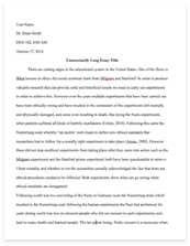
As the camshaft rotates, cam lobes, attached to the camshaft, interface with the engine’s valves. This interface may take place via a mechanical linkage, but the result is, as the cam rotates it forces the valve open. The spring return closes the valve when the cam is no longer supplying the opening force. Figure 1 shows a schematic of a single valve and cam on a camshaft.
Figure 1: Single Cam and Valve
Since the timing of the engine is dependent on the shape of the cam lobes and the rotational velocity of the camshaft, engineers must make decisions early in the automobile development process that affect the engine’s performance. The resulting design represents a compromise between fuel efficiency and engine power. Since maximum efficiency and maximum power require unique timing characteristics, the cam design must compromise between the two extremes.
This compromise is a prime consideration when consumers purchase automobiles. Some individuals value power and lean toward the purchase of a high performance sports car or towing capable trucks, while others value fuel economy and vehicles that will provide more miles per gallon.
Recognizing this compromise, automobile manufacturers have been attempting to provide vehicles capable of cylinder deactivation, variable valve timing (VVT), or variable camshaft timing (VCT). These new designs are mostly mechanical in nature. Although they do provide an increased level of sophistication, most are still limited to discrete valve timing changes over a limited range.
Early in the development of variable engines, Cadillac introduced its V-8-6-4 engine. This 1981 engine was based on a 6.0 liter V-8, but was capable of operating as a 4.5 liter V-6 or a 3.0 liter V-4. The engine changes were made while running and were controlled by the on-board computer’s determination of power requirements. The engine changed the number of active cylinders by adjusting the position of the rocker-arm fulcrum. To disable a cylinder, the fulcrum was moved via a hydraulic solenoid valve to the contact point of the rocker-arm and engine valve stem. This prevented the rotating camshaft from supplying enough force to open the engine valve. The computer then made adjustments to the fuel injection rates to compensate for the change in fuel requirements.
The Cadillac V-8-6-4 was the standard engine for all 1981 Cadillac models, but the engine experienced a short production run. Due to consumer complaints about the engine response and operation, especially when changing from one mode to another, Cadillac discontinued its variable engine.
As an update to the short lived Cadillac V-8-6-4, GM introduced its “Displacement on Demand” engines in their 2004 models. The concept is similar to the earlier Cadillac attempt, but this design limits the engine to operate either as a V-8 or a V-4. With the increase of computing power, GM states the design is more sophisticated, and they promise that the change from 8 to 4 to 8 cylinders will be virtually unnoticeable to the driver.
The new GM engine incorporates a special valve lifter, designed by Eaton Corporation. This lifter is a multi-shaft component capable of telescoping. A hydraulically actuated locking pin, when engaged, prevents the lifter from collapsing. This allows the cam to open the engine valve. When the locking pin is hydraulically removed, the cam simply collapses the lifter and cannot actuate the engine valve.
Instead of the cylinder operating changes offered by the new GM engine, Honda has introduced its VTEC engines to address the need for greater levels of engine sophistication. This design incorporates three cam lobes and three rocker-arms for each engine valve; see figure 2 for a schematic of the Honda VTEC. The unit locks the rocker-arms together as engine demands change. One rocker-arm is in contact with the engine valve stem and is directly responsible for the actuation of the engine valve. As engine demands change due to increased engine speed, the adjacent rocker-arms are linked, so the valve timing becomes a function of the second cam and rocker-arm pair. This process is repeated for higher rpm’s, so the third cam controls the timing of the engine valve. A hydraulic spool valve connects the rocker arms together by driving a pin through the units. The three cam lobes are designated for low, mid, and high rpm requirements. There use generates more consistent torque output and increase fuel efficiency by providing better valve timing at three different operating ranges.
Figure 2: Honda VTEC Schematic
As another approach to VVT, Lexus has developed a “variable valve timing, intelligent” (VVT,i) system for its engines. They claim to have produced the next level of sophistication by introducing continuously VVT. The on-board computer monitors the engine demands and continuously adjusts the timing and overlap of the intake and exhaust valves.
Regardless of the VVT technology differences among the leading automotive manufacturers, the prime similarity of a camshaft remains. Therefore, limitations continue, since the timing is still a function of engine speed.
These limitations have initiated research into Camless engine technology. The following section outlines some recent accomplishments of other researchers in an attempt to develop truly independent VVT.
Chapter Three: Working of Camless Engine
Engine valve actuation is achieved through the following procedure. An electric impulse from the control hardware will cause the piezoelectric stack to expand. This linear expansion will be transferred into movement of a hydraulic spool valve. The slight movement of the spool valve will divert hydraulic fluid and pressure to one side of a hydraulic amplifier. The sudden increase of pressure in the hydraulic amplifier will be transmitted into linear motion by means of a piston. The movement of the piston acts as the actuator and is directly attached to an engine valve.
Variable valve timing is achieved by varying the input voltage signal to the piezoelectric stacks. This variance alters the speed of response and deflection of the stacks. Therefore, the movement of the spool valve is varied and alters the flow of hydraulic fluid. It is this combination that allows for the independent control of valves, their displacement, and their opening and closing velocity.
The system outlined above is required to overcome the displacement limitations of the piezoelectric stack, while exploiting its efficiency and ease of accurate control. The piezoelectric will offer the needed response for precise rapid changes in direction, but it cannot deliver the force over the required displacement needed for use as an engine valve actuator. Therefore, hydraulics is introduced as a proven technology, capable of actuating the engine valves.
Chapter Four: Literature Review
Originally, camless engines were developed for use as a design aide to automotive engine manufacturers. The use of a camless engine allowed the engineer to experiment with valve timing as a means of designing cam profiles. These early units were not limited by dimensional or power consumption restraints. Instead, they were solely developed for laboratory use as a design tool.
Aside from laboratory use, history shows that the idea of a camless internal combustion engine had its origins as early as 1899, when designs of variable valve timing surfaced. It was suggested that independent control of valve actuation could result in increased engine power. More recently, however, the focus of increased power has broadened to include energy savings, pollution reduction, and reliability.
To provide the benefits listed above, researchers throughout the previous decade have been proposing, prototyping, and testing new versions of valve actuation for the internal combustion engine. Their designs have taken on a variety of forms, from electro-pneumatic to electro-hydraulic. These designs are based on electric solenoids opening and closing either pneumatic or hydraulic valves. The controlled fluid then actuates the engine valves. Much of the remaining documentation deals with either the control of the solenoids or the computer modeling of such control systems. The research on the control of the solenoids is crucial since their precision and response is a limiting factor to the development of earlier camless valve actuators.
A comprehensive project using solenoid control of pneumatic actuators was completed in 1991. This research included the development of the actuators, a 16 bit microprocessor for control, and comparative testing between a standard Ford. 1.9liter, spark ignition, port fuel injected four cylinder engine and the same engine modified for camless actuation. Testing compared the unmodified engine to that of the same engine, altered to include eight pneumatic actuators in place of the standard camshaft.
The actuators used during the research required an off-engine power source because an engine mounted compressor was not feasible. The researches found that for engine operation at 1500 rpm, the eight actuators used a total of 2.5 kW of power. This compares very high to the 140 watts of power consumed by comparable production engines. As Gould et al. states, their work cannot be considered feasible for implementation due to the high power requirements of the actuator.
For their project, pneumatic actuators were chosen after running comparison tests among different methods. Pressurized air was chosen due to its low mass, allowing fast response and stability over a broad temperature range. The researchers found that hydraulic systems had sluggish response, especially at low temperatures.
The pressurized air was controlled by electromagnetic valves. All flow path distances were minimized to increase the response time of the actuator by reducing the volume of air required for actuation. The pressurized air opened the engine valves based on the timed electrical signal input to the “electromagnetic latch.” Residual air was compressed during valve seating and provided a means of slowing the valve for a soft seat.
The researchers concluded that the test engine produced approximately 11% greater torque at low engine speeds (below 2000 rpm) compared to a conventional engine. Furthermore, the camless engine was capable of reducing emission gasses, specifically “brake specific nitrous oxide emissions” (bsNOx), but only by degrading the combustion process.
In 1996 the next generation of camless engine was completed at the Ford Research Laboratory by, principally, Michael Schechter and Michael Levin. Ford’s work has taken a detailed look at the plethora of parameters associated with consistent, reliable engine operation. The first half of the paper describing their work is focused on the base parameters of valve timing and overlap. This data will serve as beneficial information during the further development of the prototype at the University of South Carolina.
Beyond the basics, Schechter and Levin introduce a new concept of the hydraulic pendulum. It is stated that the use of a hydraulic pendulum decreases the system’s energy consumption by converting the kinetic energy of a closing valve into potential energy stored in the pressurized fluid. This reduces the energy required for pumping the hydraulic fluid. Through this conversion of energy, the authors predict that a 16-valve, 2.0 L engine will consume about 125 W to operate at light loads.
The hydraulic pendulum also allows for the solenoid-based-system to slow valve velocity. This results in soft seating the valve and is a favorable attribute of the new system. Another benefit is the ability to vary the opening and closing velocity of the valve. This allows for increased variation to engine valve parameters.
A schematic of the hydraulic pendulum is shown in Figure 3. High and low pressure hydraulic reservoirs are connected to the engine valve’s actuating piston. The control of this fluid is accomplished by means of two solenoids and two check valves. High pressure fluid is always in contact with the lower side of the piston, and either high or low pressure fluid is in contact with the upper side of the piston. The difference in pressure contact area is utilized in conjunction with the hydraulic pressure to vary the actuating forces.
Figure 3: Hydraulic Pendulum Schematic
The authors provide a detailed description of the valve actuation cycle. This is summarized as follows. To open the engine valve, the high pressure solenoid opens to allow high pressure hydraulic fluid into the upper chamber. Due to the difference in pressure contact area, the valve opens. Next, the high pressure solenoid closes, but the valve’s momentum continues to open the engine further. This causes a reduction of pressure in the upper chamber and allows the low pressure check valve to open. The engine valve decelerates as it pumps the high pressure fluid from the lower cavity back to the high pressure reservoir. This process both slows the valves and recovers some energy by converting the kinetic energy of the engine valve into potential energy in the high pressure fluid. Once the upper cavity pressure equalizes with the low pressure reservoir, the check valve closes and the upper cavity fluid is static. This allows the engine valve to be held open.
Closing the valve is initiated by the opening of the low pressure solenoid valve. The engine valve accelerates toward its closed position based on the force differential between the high pressure lower cavity and the low pressure upper cavity. The upper cavity fluid is pumped back toward the low pressure reservoir. Energy is again recovered and the engine valve is soft-seated through a similar deceleration process. By closing the low pressure solenoid valve, the upward momentum of the engine valve pressurizes the upper cavity fluid. This increase in pressure opens the high pressure check valve and allows the upper cavity fluid to be pumped back to the high pressure reservoir. Again, energy is converted from kinetic to potential and the valve is decelerated.
The best timing of this process would allow for the kinetic energy of the engine valve to be exhausted exactly when it closes. However, the researchers provide an alternative to such precision. Instead, they suggest stopping the engine valve just prior to contact with the seat, and then briefly opening the high pressure solenoid to complete the cycle.
Through the use of a hydraulic pendulum, a complete four cylinder ICE was produced and found some success. However, the system is complicated and requires multiple components. The use of a hydraulic pendulum requires two solenoids and two check valves per engine valve and both a high pressure and low pressure hydraulic fluid supply. (Schechter et al. state that two solenoids can run a pair of valves as-long-as the pair is synchronized. However, this detracts from the concept of independent valve control.)
The camless engine developed by Ford and described above was then enhanced at the University of Illinois at Urbana-Champaign. The focus of the project was to advance the hydraulic-pendulum-based CLE actuator by developing an adaptive feedback control. Their research is focused on the electronics and algorithms of data acquisition and control and extends beyond the scope of the current phase of research here at the University of South Carolina. However, as a comparison, some of the results are presented here. The complete system was limited to operating at 3000 rpm. Valve lift greater than 5 mm could not be consistently controlled.
There have been a few attempts at developing production models of Camless engines, most notably by Ford, but the use of solenoids has impeded their implementation. Using solenoids to control hydraulic fluid and ultimately the opening and closing of the engine valves introduces its own limitations. The solenoids consume considerable energy and are a binary control device – they are either on or off. Therefore the hydraulic fluid, controlled by the solenoids, is either flowing or blocked. This design allows for some variance of valve timing, but is still limited by the response capabilities of the solenoids. Furthermore, it cannot directly address valve velocity or displacement changes.
The development of the Camless engine overcomes these limitations through the use of piezoelectric stacks, a spool valve, and a hydraulic amplifier instead of solenoids. This combination results in a device capable of nearly infinitely variable valve timing, altered valve displacement, and controllable valve velocity.
Chapter Five: Conceptual Development
The concept was to use piezoelectric stacks to provide the displacement of a hydraulic spool valve. The movement of the spool valve would control the flow of hydraulic fluid. To utilize the hydraulic fluid flow from the spool valve, a hydraulic amplifier would be required. This would create the needed force and displacement for actuating an ICE valve. The original anticipation of design requirements presented during the conceptual development phase was stated as follows.
• ICE valve travel requires 8 mm. Design the system for 10 mm.
• Forces encountered will be due to internal pressure within the ICE cylinder and from the valve closure spring. Design for 8 bar acting on a valve head diameter of 28 mm and a spring rate of 35 N/mm.
• ICE speed of 6000 rpm. This equates to valve actuation of 50 Hz.
• Develop control for the system that can vary valve displacement velocity and timing.
As the ICE valve opens, the forces due to pressure reduce dramatically while the spring force increases linearly. This is shown pictorially in Figure 4.
Figure 4: Resistive Engine Forces vs. Valve Displacement
The spring is designed to close the ICE valve when no force is being applied to open it. This is similar to existing engine valves, but ultimately may prove to be an obstacle to overcome. Even during the conceptual development, the replacement of spring-return with hydraulic-return was discussed. Figure 5 shows a schematic of the engine valve with a spring return. This is similar to the valve used on the test rig.
Figure 5: Engine Valve Schematic
The use of a compression spring, as shown in Figure 2, allows for thermal expansion of valve components while maintaining valve closure. If the spring is to be removed, the control system must be able to monitor the seal integrity and accommodate any displacement changes due to thermal expansion. During proof of concept testing, a spring return was maintained, as to not
introduce further control complexity.
Aside from the provided spring return valve accompanying the test rig, the other major design constraint was the hook-up requirements for connecting to the spool valve. The existing spool valve had a four port interface based on ISO 4401: Hydraulic Fluid Power – Four Port Directional Control Valves – Mounting Surfaces. Figure 6 represents a schematic of the four port interface.
Figure 6: Four Port Directional Control Valve Mounting Surface
From Figure 6, it can be seen that there are four bolt holes and the four hydraulic ports labeled A, B, P, and T. These represent the following.
• Ports A and B are the output ports for hydraulic fluid. Fluid flow is directed to A or B depending on the position of the spool. For the Camless engine application, ports A and B provide hydraulic pressure to the top and bottom of the hydraulic amplifier’s piston, respectively.
• Port P is the input port. It is connected to the output of a hydraulic pump.
• Port T is the return port. It is connected to the input of a hydraulic fluid reservoir.
The concept develops a hydraulic actuator that would connect to ports A and B of the provided spool valve. By creating a hydraulic actuator based on a piston – cylinder arrangement, hydraulic fluid from ports A or B would cause displacement of the piston. This is shown schematically in Figure 7.
Figure 7: Hydraulic Actuator Schematic
As shown in Figure 7, if hydraulic pressure is introduced through port A from the spool valve, the piston will move down. Hydraulic pressure applied to port B will cause the piston to move up. Furthermore, hydraulic fluid must be able to drain out of the cylinder through the port opposite of that being pressurized. For example, as hydraulic pressure and fluid is applied through port A, the piston moves down. Since the hydraulic fluid is essentially incompressible, the fluid must be able to drain through port B.
Considering this concept, the ICE valve would simply be attached to the end of the piston. This would create linear actuation. Length of stroke would only be dependent on the piston surface area in contact with the hydraulic fluid, the pressure of the fluid, and the resistive forces associated with opening the ICE valve. The major components that make-up the camless engine actuator are two bore plates, one cylinder block, one piston, and the piezoelectric controlled spool valve. Additional elements include the fasteners, o-rings, and PTFE lip seals. The result of the camless engine actuator assembly is shown below in Figure 8.
Figure 8: Hydraulic Actuator and Mounting Block Assembly
Figure 8 shows a cutaway view of the camless engine actuator assembly. Because it is cutaway, the spool valve and the ISO 4401 port connections are not visible. In this view, the spool valve would be coming out of the paper toward the reader. The camless engine actuator assembly and mounting block were then attached to the hydraulic system. Hydraulic connections and layout are addressed in the next section.
Chapter Six: Assembly of the Hydraulic System
The camless engine actuator assembly outlined in the previous section was mounted onto the hydraulic system. Hydraulic connections were made via the standard hydraulic threaded connection ¼ – 19 BSP (British Straight Pipe). The system flows hydraulic fluid from a pump and back to a reservoir and is a self contained scheme.
Hydraulic fluid is pumped through a ball valve and into the side port of the cylinder block. This connection is directly routed to the P port of the spool valve. From there, the position of the spool valve determines where the pressurized fluid goes. In the neutral position, the fluid is dead-headed, and aside from any leakage past the spool, the fluid is static. See Figure 9.
Figure 9: Hydraulic Amplifier Schematic
When the spool valve translates up, fluid flows through the B port and pressurizes the upper cavity of the cylinder block. This pressurization results in the downward translation of the piston. In turn, the engine valve is being opened as the piston translates down. This is shown in Figure 10.
Figure 10: Hydraulic Amplifier – Spool Valve Up
The opposite occurs as the spool valve translates down. Fluid flows through the A port and pressurizes the lower cavity of the cylinder block. This pressure causes the piston to rise and allows the engine valve to close. See Figure 11.
[pic]Figure 11: Hydraulic Amplifier – Spool Valve Down
Drainage of fluid from the cylinder block takes place through the A or B port, whichever is not being pressurized by the spool valve. As the piston translates toward the non-pressurized port, hydraulic fluid is forced back into the spool valve. This fluid is then routed directly to the T port (drain) and returns to the reservoir. From the reservoir, the fluid is pumped back into the system, and the process repeats.
Conclusion
It is the ability to vary valve timing that will provide tremendous improvements to the next generation of internal combustion engines. An engine will be capable of providing increased power when needed, increased fuel efficiency when allowable, and overall reduced emissions. For example, when entering onto a busy expressway, the onboard computer will sense the need for greater power. This results in valve timing changes to alter the overlap between intake and exhaust valves. Doing so will momentarily sacrifice efficiency for power. Then, once the automobile is cruising on the expressway, the computer will alter the timing again to reduce power and increase fuel efficiency. Furthermore, the timing can be optimized for a more complete burn; therefore the engine will produce fewer emissions. Fuel economy can further be increased by shutting down unneeded cylinders. When an automobile is cruising at a constant speed, it does not require all cylinders to be operational. With this newly developed piezoelectric controlled camless technology, complete cylinders can be removed from the timing cycle.
It is this combination of hydraulics and piezoelectric stacks that constitutes a leap in automotive engine technology. A working prototype to actuate a single valve has been completed, and testing has proven that the system is a viable alternative to a camshaft.
The overall results of a complete Camless engine will provide the consumer with a vehicle that performs to expectations, but facilitates increased fuel economy. This combination is essential, since evidence shows consumers are not prepared to compromise on performance, while at the same time fuel prices continue to escalate.
References
Dobson, N. and Muddell, G., 1993, “Active Valve Train System Promises to Eliminate Camshafts,” Automotive Engineer February/March 1993.
General Motors – GM and the Environment. May 21, 2001. General Motors. June
13, 2001.
Ladd, D; Camless Engine is Gaining Momentum. September 13, 1999. Siemens Automotive. July 4, 2000 .
Lexus – Variable Valve Timing a First in an SUV. Autoworld. June 18, 2001 .
Mori, Kaz. Honda’s High-Output LEV Engine Home Page. Honda. June 13, 2001 .


