Step Down DC to DC Converter
- Pages: 2
- Word count: 413
- Category: Cell Phone College Example
A limited time offer! Get a custom sample essay written according to your requirements urgent 3h delivery guaranteed
Order NowIn our world today, cellphones, and laptops are widely used. For some, these things are so important especially for students and employers who work from office. These devices are usually operated with battery. A DC to DC converter is an electronic circuit which converts a source of direct current (DC) from one voltage level to another. DC is not easily being stepped up or down. One of the applications of this DC to DC converter is stepping down the voltage. In this experiment a Step down DC to DC converter was created. Here, the output voltage will become smaller than the input voltage. This type of applications is the one used for cellphones and laptops.
Objectives
The purposes for the construction of this Step down DC to DC Converter are:
* To design a DC to DC converter that will have a varying low voltage output. * To be able to apply the theories, principles, and concepts learned from the
courses, Electrical Circuits and Laboratory.
* To be able to connect the Step down DC to DC Converter designed in the breadboard and printed circuit board (PCB).
Scope and delimitation
This experiment only makes the output voltage to step down. The output voltage can’t be bigger than the input voltage.
Methodology
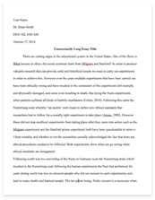
I. Schematic Diagram
II. How the circuit works
A 555 timer used to generate a square wave. It produces a negative voltage which is relative to the negative terminal. When the output of the 555 timer (referring to pin 3) became positive, the electrolytic capacitor (22 µf) charges Diode (D1) about 8V. When the output turn to the ground, the electrolytic capacitor (22 µf) discharges through the second diode (D2) and it will charge the second electrolytic capacitor (10 µF) until it became a negative voltage The negative voltage can be rise up to -7V the 5.1 volt zener diode is serves as a regulator which limit the voltage to rise up.
Materials Used
Quantity| Units| Materials|
1| | 555 timer|
1| 5k Ω| resistor|
1| 33k | resistor|
1| 0.022 µf| Electrolytic capacitor|
1| 100 µf| Electrolytic capacitor|
2| 2n222a| Regulating Diode|
1| 5.1 V| Zener Diode|
1| 9 V| Battery|
1| 22 µf| |
2| | Diode|
Recommendation
This experiment only makes the output voltage to be low. It can be improved by making the voltage to step up and step down in one circuit or step up only.
References
1) http://www.jaycar.com.au/images_uploaded/dcdcconv.pdf
2) http://www.next.gr/power-supplies/ac-dc-dc-dc/9V-to-5V-converter-schematic-with-555-l8185.html


