The LM386 Audio Amplifier Circuit
- Pages: 2
- Word count: 383
- Category:
A limited time offer! Get a custom sample essay written according to your requirements urgent 3h delivery guaranteed
Order NowCharacteristics
The LM386 IC functions as a low voltage audio power amplifier. It is a chip that was specifically designed as an audio driver and it can handle higher currents. It has a preset voltage gain of 20, which can be improved into the range of 20 and 200 by strategically placing a peripheral series RC circuit between the pins 1 and 8. Its gain-frequency curve can be altered with some external feedback components. It has a wide supply voltage range, running from 4 volts to 12 volts.
Diagram
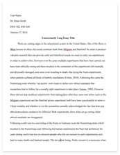
The circuit below is an example of an audio amplifier that uses the LM386 chip. It is in a high-gain configuration, with A = 200. To attain a maximum gain of only A = 20, omit the 10 uF connected from pin 1 to pin 8. Highest amplification gains around 20 to 200 could be achieved by adding a preferred resistor in series with the same capacitor. The audio amplifier’s variable gain is controlled by the 10k potentiometer. It will vary from zero to the maximum gain.
Figure 1.0 An example LM386 audio amplifier schematic diagram.
Gain control
The ability to control the amplifier’s gain makes the LM386 a more versatile amplifier. The pins 1 and 8 are used in controlling such gain. With pins 1 and 8 open the 1.35 kW resistor sets the gain at 20. Putting a capacitor across the IC’s pin 1 and 8 will bypass the 1.35 kW resistor, causing the gain to increase up to 200. If a resistor is placed in series with the capacitor, the gain can be set to any value from 20 to 200. It can also be done by coupling a resistor from pin 1 to the circuit’s ground.
Frequency response
The audio amplifier’s frequency response is flat from 30 Hz to over 20,000 Hz. Supplementary external components can be connected in parallel with the internal feedback resistors to modify the gain and frequency response for specific applications. For example, we can compensate poor speaker bass response by frequency shaping the feedback path. This is done with a series RC from pin 1 to 5 (paralleling the internal 15 kW resistor)
Reference:
LM386 Low Voltage Audio Power Amplifier Datasheet, National Semiconductor, March 1997


